
Low power electronics - a new challenge
Traditionally all of my electronics projects have been mains powered, either direct or via a wall-wart style power supply. Recently I have had need to work on systems that need to be powered by batteries, this is a whole new world of challenges….
What does low power mean…?
Low power can mean different things for different applications, a washing machine that only consumes 0.5kWh per cycle could be considered low power, in this case we are referring to battery powered applications. Battery applications need to consume as little as possible to preserve battery life, especially important in remote monitoring situations where changing batteries would be very difficult or expensive.
The applications…
There are many applications for low power but my interests are in the IoT (Internet of Things) area. I have been working on local environmental monitoring around the home and more recently counting people in the great outdoors (see here for more information).
How do we achieve low power…?
The easy answer is to consume no power, the real answer is slightly more complicated.
Most modern systems contain micro-controllers (MCUs), these come in a wide variety of specifications and abilities, the trick is to find the best one that provides everything your application requires.
There are whole families of MCUs that are geared towards low power while providing everything else needed. I originally used the microchip XXXXXX ultra-low power devices but switched to the atmega328p range as this is still very low power and has vastly better community support thanks to it being widely used in the Arduino range of boards.
To save power most modern MCUs have various sleep modes, these can either shut down parts of the device or pause everything while maintaining the device state.
Where to start, the hardware….
As already stated I have targeted the ATmega328p from Atmel as it allows be to use the Arduino environment for rapid development before deploying to my own hardware. It has excellent community support and is low power.
Developing with off the shelf Arduino boards…
You will never achieve ultra low power with an off the shelf Arduino board, not without some modifications anyway.
Most Arduino boards have a number of features on board to make our lives easier, a power LED, a voltage regulator and a USB to UART convertor. Each of these features consumes power all the time, and often are selected on the base of cost rather than power consumption.
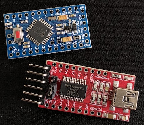
Select an Arduino that has as fewer of these extra as possible, I chose the PRO-Mini as it does not have the on-board USB interface. This does mean using an external USB/serial interface but these are readily available.
This board is a generic 8MHz 3.3V variant from Amazon.
The next step is to remove the power LED and the regulator, you will need to power the board from a 5V or 3.3V supply (depending on the board voltage).
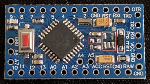
During this process I measured the current using the power profiler kit II. The board was programmed with the basic blink sketch and the output LED was still fitted which accounts for the stepped output on the plots
					// Basic Arduino blink sketch
// the setup function runs once when you press reset or power the board
void setup() {
  // initialize digital pin LED_BUILTIN as an output.
  pinMode(LED_BUILTIN, OUTPUT);
}

// the loop function runs over and over again forever
void loop() {
  digitalWrite(LED_BUILTIN, HIGH);   // turn the LED on (HIGH is the voltage level)
  delay(1000);                       // wait for a second
  digitalWrite(LED_BUILTIN, LOW);    // turn the LED off by making the voltage LOW
  delay(1000);                       // wait for a second
}
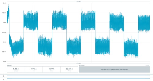
This is the power consumption on the board with the LED and regulator fitted, the 5V power supply was connected to the raw input.
The current varies between 5.7mA and 7mA as the LED goes on and off.
Powered by 1500mAh AA type batteries this would run for around 230 hours.
This is the power consumption on the board with the LED removed but the regulator still fitted, the 5V power supply was connected to the raw input.
The current varies between 4.2mA and 5.5mA as the LED goes on and off.
Powered by 1500mAh AA type batteries this would run for around 310 hours.
This is the power consumption on the board with both the LED and the regulator removed, the 3.3V power supply was connected to the VCC input.
The current varies between 3.8mA and 5.2mA as the LED goes on and off.
Powered by 1500mAh AA type batteries this would run for around 333 hours.
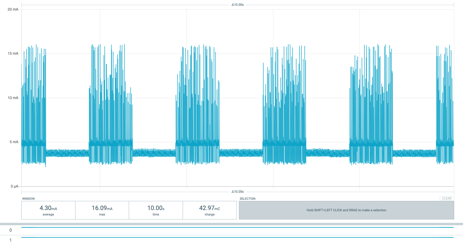
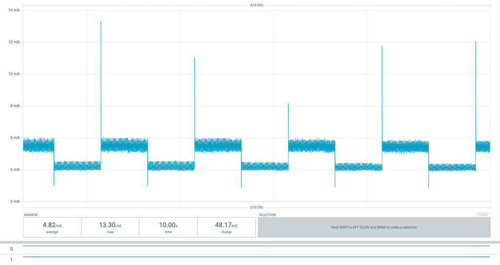
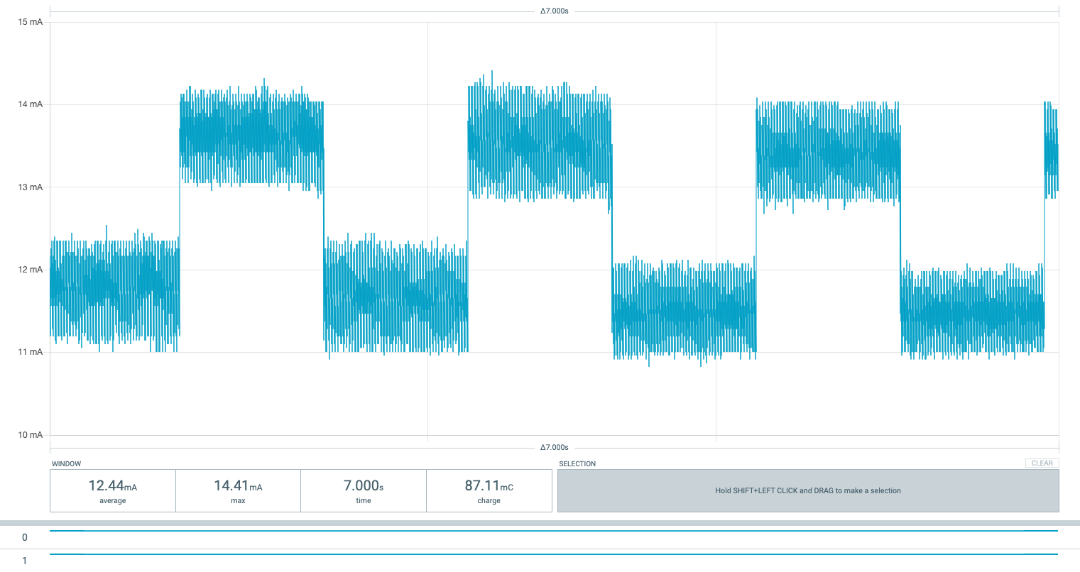
Just for reference, this is an Arduino nano complete with regulators, LEDs and USB interface and a 5Volt supply.
The current varies between 11.5mA and 13.5mA as the LED goes on and off.
Powered by 1500mAh AA type batteries this would run for around only 120 hours.
This is pretty much as low as you can go before we start enabling the power saving features of the micro-controller. In 1500mAh AA battery we could run for around 333 hours up from 230 hours with the unmodified circuit.
					#include <avr/sleep.h>
#include <avr/wdt.h>

// The setup function
void setup()
{
  // Set all outputs low
  for (byte i = 0; i <= A5; i++)
  {
    pinMode (i, OUTPUT);
    digitalWrite (i, LOW);
  }
}

// watchdog interrupt
ISR (WDT_vect)
{
   wdt_disable();  // disable watchdog
}

// The loop function
void loop()
{
  digitalWrite(LED_BUILTIN, HIGH);   // turn the LED on (HIGH is the voltage level)
  snooze();
  digitalWrite(LED_BUILTIN, LOW);    // turn the LED off by making the voltage LOW
  snooze();
}

// The sleep function
void snooze()
{
  // disable ADC
  ADCSRA = 0;
  // clear various "reset" flags
  MCUSR = 0;
  // allow changes, disable reset
  WDTCSR = bit (WDCE) | bit (WDE);
  // set interrupt mode and an interval
  WDTCSR = bit (WDIE) | bit (WDP2) | bit (WDP1);    // set WDIE, and 1 second delay
  wdt_reset();  // pat the dog

  set_sleep_mode (SLEEP_MODE_PWR_DOWN);
  noInterrupts ();           // timed sequence follows
  sleep_enable();

  // turn off brown-out enable in software
  MCUCR = bit (BODS) | bit (BODSE);
  MCUCR = bit (BODS);
  interrupts ();        // guarantees next instruction executed
  sleep_cpu ();
  sleep_disable();      // cancel sleep as a precaution
}
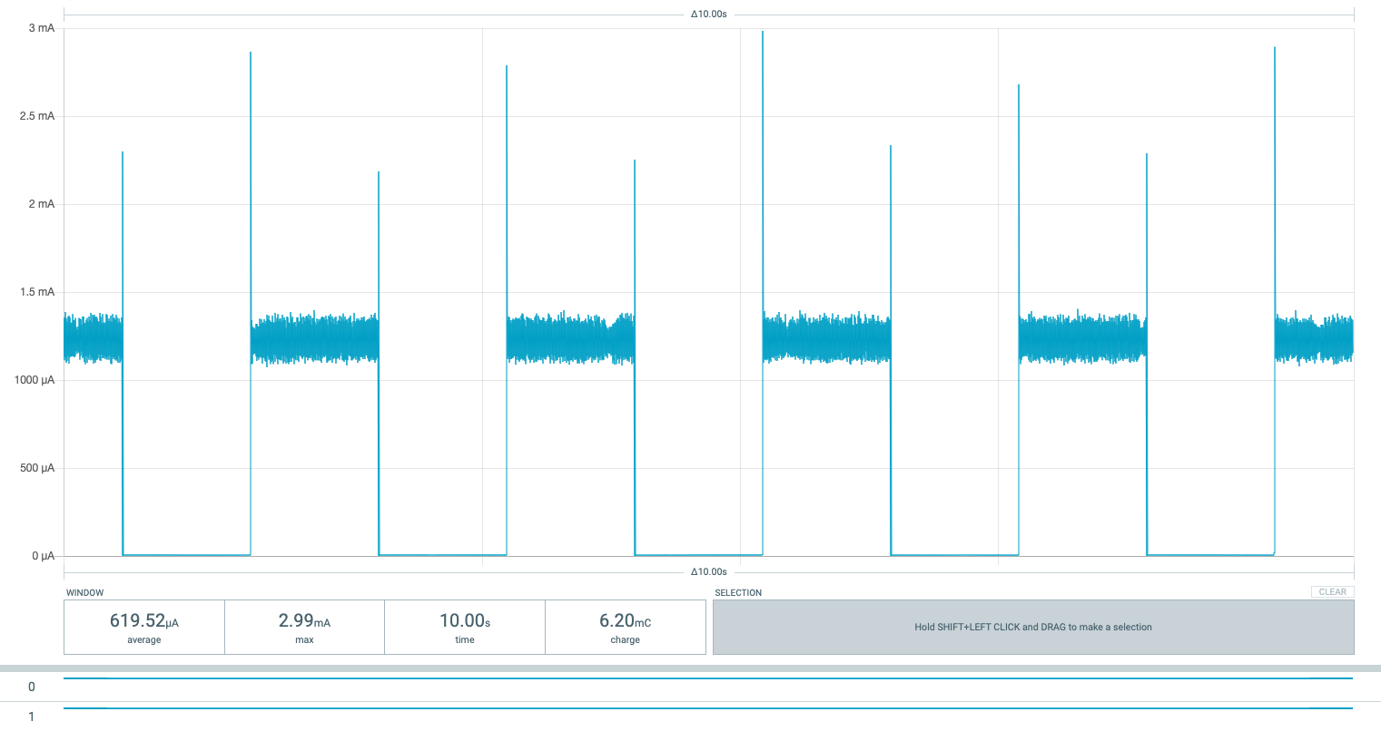
This is the power consumption on the board with both the LED and the regulator removed, the 3.3V power supply was connected to the VCC input.
Th code is now running the code above and sleeps the majority of the time.
The current now varies between almost nothing and 1.2mA as the LED goes on and off.
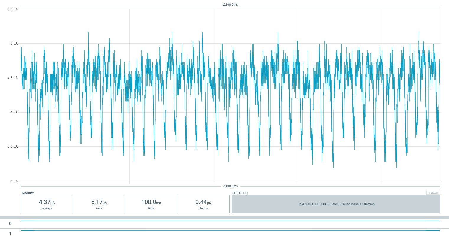
Zooming in to the low area of the plot we can see the low power is around 4.3uA.
The final figures are:
- New board: 5.7 mA
- With power LED removed: 4.2mA
- With LED and regulator removed and powered directly from 3.3V: 3.8mA, this is the minimum running current of the board.
- With LED and regulator removed and powered directly from 3.3V in deep sleep: 4.3uA.
As you can see we have saved considerable power, if we were to power our device batteries the lifespan would be very different.
With 4*1.5V AA (1500mAh) batteries we would get around 16 days of battery life.
With 2*1.5V AA (1500mAh) batteries (we only need 3V) we would get around 38 years of battery life. This is is your device constantly sleeps, it will have to wake up to do some stuff once in a while so this time will be shorter. If, for example, you woke up every minute for 1 second then the battery would last around 2.5 years, wake up every 5 minutes for 100ms then you are looking at 29 years!
Notes:
- This still has the watchdog timer running, the current could be lower still if the watchdog was not used, but you would need another method to wake the micro-controller from sleep.
- This also has all the components on the board not removed, there will be some leakage in the capacitors etc.
- This is a generic pro-mini from Amazon, I do not know the source of the device on this board, it could be a counterfeit as they do exist and in general do not handle the low power modes well (. That said this is pretty close to the data sheets so so I assume it is a legitimate part in this case.
- Thanks to Nick Gammon for his helpful information, I have borrowed some code from him for this page.
16MHz or 8MHz, 5V or 3V?
The 328P can operate across a wide range of voltages, 1.8-5.5V, but not all voltages can reach the higher clock rates of the device. Most Arduino 328 boards come with a 16MHz clock speed and are powered by 5V, for the pro-mini there is also a 8MHz/3.3V option.
The advantage of the 3.3V operation is that it takes significantly lower power, the disadvantage is that 8MHz is the maximum clock rate and not introduce possible issues.
I went for the 8MHz/3V option, it is only half the clock rate, more than fast enough for my needs, and can be powered directly from batteries (more on batteries later).
It is possible to have an even lower clock frequency for even lower power, I have never tried this though.
Gotcha! There may be a temptation to go for a really low clock speed to save the most power. This will always be a trade off and there comes a point when the quiescent current of the powered up MCU is more than the savings due to low clock speed.
Hardware considerations/gotchas!
The micro controller is not the only place power can be lost. External sensors, components, assigned IO can all drain current. Some things to look out for:
- External sensors, many sensors are ‘intelligent’ and work independently of the MCU, this means that they are always consuming power, often several mAs. Select sensors that have a low power mode, the BME280 for example, has a runtime current of almost 4uA, but a sleep current of only 0.1uA.
- Watch those unused I/O pins on the MCU. Leaving the unused pins on a micro-controller floating can draw much more power than setting them to an output and setting the high or low.
- Voltage regulator quiescent current. All voltage regulators have a quiescent current, this can be quite high, 6mA in a typical 7805, so look for a regulator with a low quiescent current if you must use a regulator. I use a MCP1702, this has a 2uA quiescent current but can only handle 13.2V and 250mA max.
- Component leakage. Many other components especially capacitors have a leakage current, this is often very low but all needs to be taken into account. I have found tantalum capacitors are significantly lower leakage than electrolytic. FETS have lower leakage than transistors.
Firmware considerations/gotchas!
The firmware is where most savings can be made, some things to look out for:
- Go into sleep/deep-sleep wherever possible.
- Disable as many internal peripherals as possible while sleeping and at runtime if they are not used.
- Initialise any peripherals correctly to observe the sleep conditions.
- Disable brownout detection if it is not used.
- Disable the watchdog if it is to used.
- Optimise all code to run as quickly as possible, especially so for code that is run regularly.
Measuring power consumption…
This is a tricky area, measuring the current consumption of a device that sleeps (<1uA) and then runs for a time (>3mA) can not be measured by using a standard multi-meter due to the burden voltage. As multi-meters measure current by measuring the voltage dropped across a resistor the extreme difference between sleep and awake currents will not work. A low current setting will drop to many volts when the device wakes and it will reset.
There are tools you can obtain to help measure these extremes of power:
- Micro current gold. This amplifies the current to be output to a multi-meter or scope. It has a lower burden voltage but due to the manual range selection can still introduce losses into the supply line. A good price at around AU$79 but often out of stock.
- Current ranger, This is very similar to the Micro current gold but has qutorange switching. The auto switching changes the range so that the burden voltage never becomes an issue. It also has the option of an OLED display to show the current data and can send the live data via the USB port or via bluetooth. I have one of these and it works well. More expensive than the micro-current gold but a) it’s features are worth the extra and b) it is available!
- The OTII, seems to be the best you can get. This is a power supply with integrated power monitoring and uses PC software to provide some very impressive functionality. It does come at a high cost though (£500+)
- Power Profiler Kit II. I have only just discovered this and it comes from Nordic Semiconductor, maker of the the NRF5x range of bluetooth devices. This seems to offer much of the functionality of the Otii at a much lower cost (around £77). I have just brought one and have only run some brief test. It seems really good, easy to use, built in logic analyser wide current range 20nA-1A. Works with Windows, Mac and I believe Linux as well. It can act as a power source from the USB port. The only limitations I have found so far are the 5V maximum, some of my circuits use a 7.2V battery pack so I have to revert back to the current ranger for this.
- There is also the Joulescope, I have no experience of this and it is quite expensive ($799+).
Any of these should help analyse the current usage of your project. Andreas Spiess has several videos on this subject and a recent one covers all the devices above.
And if I don’t have access to any of these devices…?
Before I had the current ranger I used a multimeter, it is not quite as accurate and does involve tweaking the firmware for each type of test, but gives a pretty close measurement.
High current parts of the code:
- Don’t sleep the device
- Put it in a tight loop so the code it running all the time
- Toggle an output each time your code goes through the loop (do not connect to an LED, this will increase the current!)
- Measure the current as you would normally with a multi-meter and view the digital output with s scope to see how long the code takes, if you don’t have a scope then the frequency measurement of your multi-meter will give an indication of the loop time. From the loop time and the power you can workout the high current part of the power consumption.
- If you have several different routines that get called at different times (a general tick, and hourly functioning and a daily function for example) then you would need to repeat this for each function.
Low/sleep parts of the code, this is a little more tricky:
- Modify the code to sleep for much longer (several seconds).
- Toggle a spare output, possibly drive an LED when in high current mode.
- Connect the multi-meter in low current range.
- Short out the meter (so the board gets the full current)
- Observe your spare output and once it goes into low power/sleep mode remove the short from the meter, you should now see the sleep consumption current. As long as you can sleep for several seconds your meter should show a reasonably accurate measurement. The MCU will possibly reset once it wakes up again.
- You do not need the low power time period as you should be able to work this out from the remaining time after you have subtracted the high current time.
Real world figures…
I generally use my own PCBs for measurements but in general the values from my boards are very close to the modified Arduino development boards.
Most projects use the watchdog to wake the system up and have the brownout detector enabled in the configuration but disabled during deep sleep.
All boards have a 8MHz resonator for the clock and run from around 3.3-3.6V (either via 3.3V regulator or direct 3.6V from the battery).
The running current is around 3mA and the sleep current is less than 10uA with no sensors connected.
Whats next…?
There is still much to cover, connectivity, ESP32, GSM, WiFi etc. I will add more code and hardware details in other posts soon.